Manufacturers
- Abracon
- Adam Tech
- Aerospace, Defense & Marine
- Agastat
- AIC
- AKM Semiconductor
- Alcoswitch
- Allegro
- Alps Electric
- Altera
- AMI Semiconductor
- AMP
- ams
- Analog Devices (ADI)
- Aptina Imaging
- Atmel
- Avago / Broadcom
- AVX
- Axicom
- Bccomponents
- Beyschlag
- BI Technologies
- Bourns Inc.
- Bowei Integrated Circuits
- Bridgelux
- Buchanan
- California Micro Devices
- Catalyst Semiconductor
- CGS
- Cirrus Logic
- Citizen Electronics
- CML Microcircuits
- Coiltronics
- Cooper Bussmann
- Corcom
- Core Logic
- Cree
- CSR PLC
- CTS
- Cypress Semiconductor
- Dale
- Data Image
- Deutsch
- Diodes Incorporated
- DOMINANT Opto Technologies
- E-T-A
- Eaton
- ECS
- Edison Opto
- Elcon
- EPCOS
- Epistar
- Epson
- Everlight Electronics
- Exar
- Fairchild Semiconductor
- FCI
- Freescale Semiconductor
- Fremont Micro Devices (FMD)
- Fujitsu Semiconductor
- Fulltech Electric
- General Semiconductor
- Harvatek
- Holsworthy
- Hsuan Mao Technology
- IDT
- Infineon Technologies
- Innolux
- International Rectifier (IR)
- Intersil
- IRC
- ISSI
- IXYS-IC
- Jing Cheng Electronical
- JL World
- Johanson Dielectrics
- Johanson Technology
- JRC / NJR
- JST
- KEC
- Kilovac
- Kingbright
- Kyocera Industrial Ceramics
- LEDiL
- Linear Technology / ADI
- Lite-On Technology
- Littelfuse
- Lumex
- Lumileds
- Luminary Micro
- Luminus Devices
- Macronix
- Maojwei / ZJPT
- Maxim Integrated
- MCC
- Mean Well Enterprises
- Microchip Technology
- Micron
- Microsemi
- Mini-Circuits
- Molex
- Murata Manufacturing
- Murata Power Solutions
- MWT
- National Semiconductor
- Nichicon
- Nippon Chemi-Con
- NJR / JRC
- NVE
- NXP Semiconductors
- OEG
- Omnivision
- ON Semiconductor
- Optek Technology
- Optrex
- OSRAM Opto Semiconductors
- OTAX
- Panasonic
- Peregrine(pSemi)
- Potter & Brumfield
- Power Integrations
- PowerStor
- Preci-Dip
- Prewell
- Products Unlimited
- Pulse Electronics
- PulseCore Semiconductor
- Qorvo
- Raychem
- Renesas Electronics
- RFMD
- Richtek Technology
- ROHM Semiconductor
- Rubycon
- Samsung Electro-Mechanics
- Samsung Semiconductor
- Schaffner
- Schrack
- Seiko Instruments, Inc. (SII)
- Semtech
- Sensata
- Seoul Semiconductor
- Sfernice
- Sharp Display
- Sharp Microelectronics
- Silicon Labs
- Siliconix
- Skyworks Solutions
- SoniCrest / JL World
- Spansion
- Sprague
- Stanley Electric
- STMicroelectronics
- Sunny Electronics
- Susumu (SSM)
- Taimag
- Taiyo Yuden
- TDK
- TDK-Lambda
- TE Connectivity
- Teccor
- Texas Instruments (TI)
- Thin Film
- Tianma Micro-electronics
- TOCOS
- TOKO
- Toshiba Electronic Components
- TT Electronics
- Tusonix
- TXC
- Tyntek
- Vishay
- Vishay Precision Group
- Vitramon
- Walsin Technology
- Weidmuller
- Welwyn
- Wickmann
- Winbond
- Xilinx
- Yageo
- Zetex Semiconductors
- ZJPT / Maojwei
News
Inductors: TDK develops downsized, compact, thin-film power inductors for automotive power circuits
2021-08-03 | Return> Supports an operation range between –55 °C and +150 °C
> Increased robustness against mechanical stress due to the resin electrode structure and thermal shocks
> Compliant with AEC-Q200 Rev D

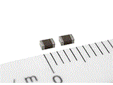
TDK Corporation has developed a series of thin-film metal power inductors for automotive power circuits. The new TFM201210ALMA inductors feature a mounting area downsized approximately 22 % from TDK’s conventional product, TFM201610ALMA (2.0 mm (L) x 1.6 mm (W) x 1.0 mm (H)). Mass production will begin in August 2021.
Demand has recently increased in ECU* mounting for the electrification of various automotive controlling functions, autonomous driving, information communication and other purposes. Downsized inductors for power circuits contribute to space-saving in a mounting substrate, at a time when quick advances in ADAS** performance increase the number of components typically used in system architectures.
In addition to its compact dimension of 2.0 mm (L) x 1.25 mm (W), this series uses the TDK proprietary metallic magnetic material as its core material. The thin-film inductors support a wide range of operating temperatures from -55 °C to +150 °C, the highest level in the industry***. Moreover, it features increased robustness against mechanical stress, such as vibrations and shocks due to the resin electrode structure.
In addition to the new items, TFM series includes a lineup of products with a rated voltage of 40 V, allowing use on an automotive power circuit side directly connected with a 12 V battery.
***Source: TDK, as of July 2021
Glossary
> *ECU: Electronic Control Unit
> **ADAS: Advanced Driver-Assistance Systems
Main applications
> Automotive camera module
> Communication module for V2X
Main features and benefits
> A compact size of 2.0 mm (L) x 1.25 mm (W) x 1.0 mm (H) to facilitate space saving
> Supporting an operation temperature range between –55 °C and +150 °C (including self-heating)
> Increased robustness against mechanical stress due to the resin electrode structure and thermal shocks
Key data
Type |
Inductance |
DC resistance |
Isat* |
Itemp** |
Rated voltage |
TFM201210ALMAR56MTAA |
0.56 ± 20 % |
49 |
3.0 |
2.8 |
20 |
TFM201210ALMA2R2MTAA |
2.2 ± 20 % |
282 |
1.2 |
1.1 |
20 |
* Isat*: Current value based on inductance variation (30 % lower than the initial L value)
* Itemp**: Current value based on temperature increase (Temperature increase of 40 °C by self-heating)
* Rated current: Current value shall be IsatMax or ItempMax, whichever is less
Source: http://www.littelfuse.com/


